CUSTOM DRIVESHAFTS
Learn How To Measure For A Custom Driveshaft
Formula D champion, Chris Forsberg to show you how to measure for a Carbon Fiber Driveshaft.

How To Measure For A Custom Driveshaft
Please see below for diagrams on how to properly measure for your configuration:
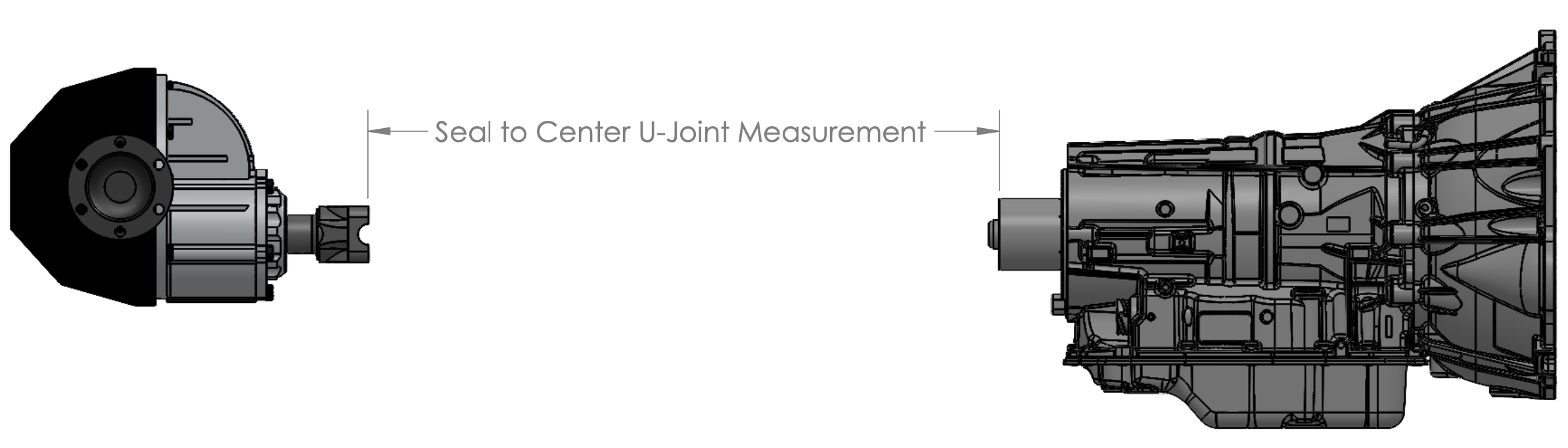
Figure 1:
(Transmission seal to Center of U-Joint) This is for vehicles with a slide in transmission yoke (TH350 / TH400 / T56 / etc.) and a pinion yoke with u-bolts or straps on the differential (Ford 9″, GM 12-Bolt, etc.):
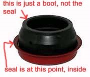
****PLEASE NOTE: Some Transmissions (T56 / T56 Magnum, TKO, etc.) have a rubber dust boot that protrudes off of the back of the transmission.
If you do not have one of these transmission types, measurements must be taken from the end of the transmission tail housing. This point will be flush with the oil seal.
When Measuring:
If you have a solid or live rear axle, measurement MUST BE TAKEN WITH REAR AT RIDE HEIGHT (The car can be lifted under the differential but make sure it has weight on the rear springs)
- We prefer your measurement to be taken from the OIL SEAL (flush with the end of tail housing). Do not measure from the tip of the output shaft or from any dust boot that may protrude from the transmission
- See below for information on measuring your pinion yoke and flange
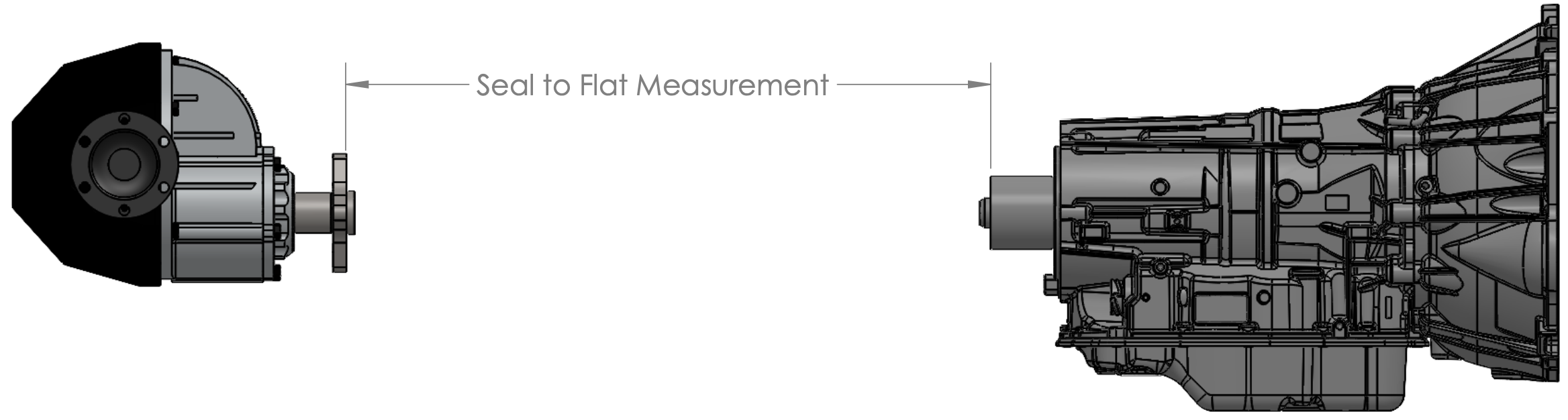
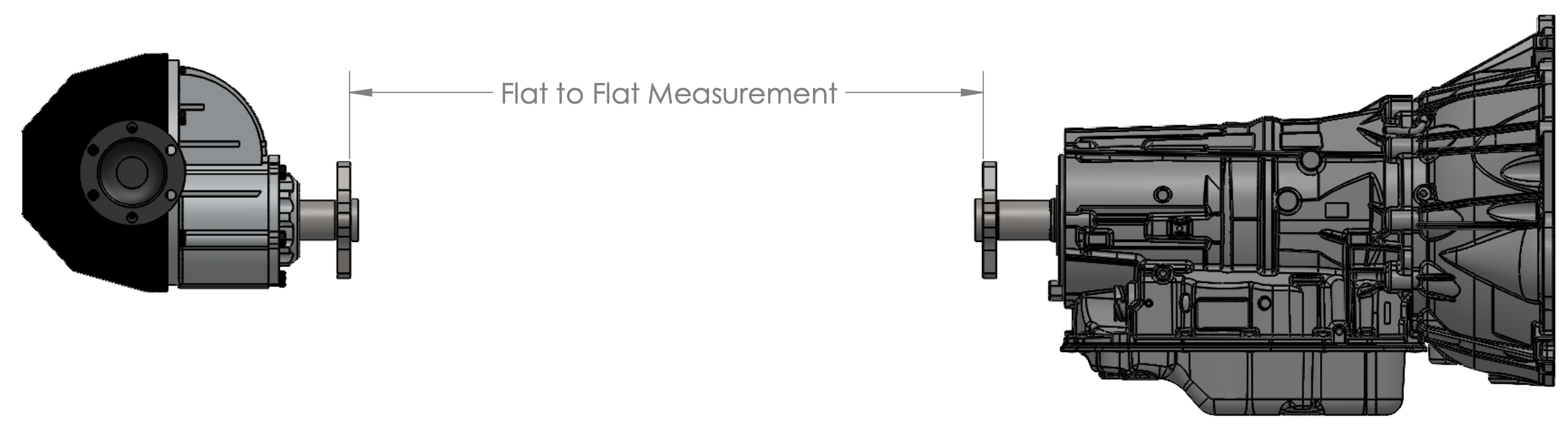
Figure 2:
(Transmission Seal to Flange)
This is for vehicles with a slide-in transmission yoke (TH350 / TH400 / T56 / etc.)
and a flat flange on the differential (can be 3-bolt, 4-bolt or 6-bolt, etc.):
****PLEASE NOTE: Some Transmissions (T56 / T56 Magnum, TKO, etc.) have a rubber dust boot that protrudes off of the back of the transmission.
If you do not have one of these transmission types, measurements must be taken from the end of the transmission tail housing. This point will be flush with the oil seal.
When Measuring:
If you have a solid or live rear axle, measurement MUST BE TAKEN WITH REAR AT RIDE HEIGHT (The car can be lifted under the differential but make sure it has weight on the rear springs)
- We prefer your measurement to be taken from the OIL SEAL (flush with the end of tail housing). Do not measure from the tip of the output shaft or from any dust boot that may protrude from the transmission
- See below for information on measuring your pinion yoke and flange
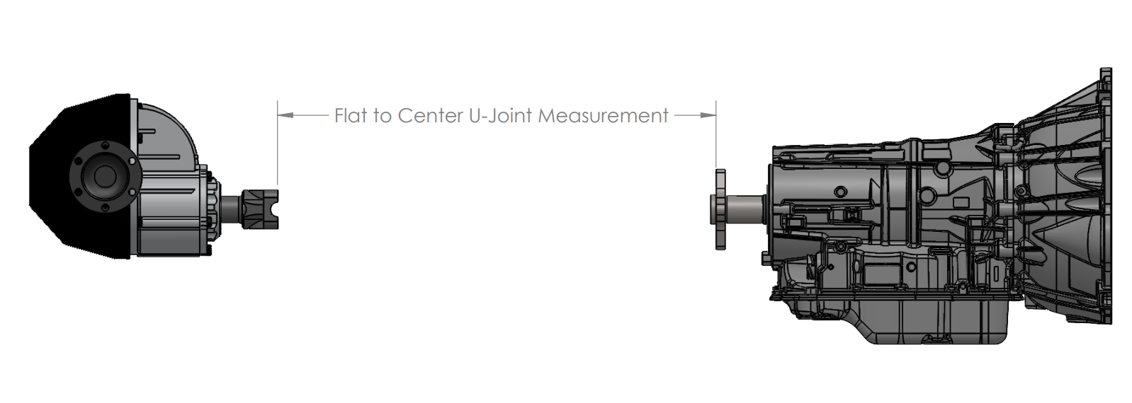
Figure 3:
(Transmission Flange to Center of u-Joint) This is for vehicles with a flat flange (can be 3-bolt, 4-bolt or 6-bolt, etc.) on the transmission and a pinion yoke with u-bolts or straps on the differential (Ford 9″, GM 12-Bolt, etc.):
When Measuring:
If you have a solid or live rear axle, measurement MUST BE TAKEN WITH REAR AT RIDE HEIGHT (The car can be lifted under the differential but make sure it has weight on the rear springs)
- We prefer your measurement to be taken from the BOLT FACE on the transmission flanges (center of U-Joint)
- ANY RUBBER GUIBO COUPLERS MUST BE REMOVED BEFORE MEASURING
- See Below for information on measuring your pinion yoke and flange
Figure 4:
(Transmission Flange to Differential Flange) This is for vehicles with a flat flange (can be 3-bolt, 4-bolt or 6-bolt, etc.) on the transmission and a flat flange on the differential (can be 3-bolt, 4-bolt or 6-bolt, etc.):
When Measuring:
If you have a solid or live rear axle, measurement MUST BE TAKEN WITH REAR AT RIDE HEIGHT (The car can be lifted under the differential but make sure it has weight on the rear springs)
- We prefer your measurement to be taken from the BOLT FACE on the transmission and differential flanges
- ANY RUBBER GUIBO COUPLERS MUST BE REMOVED BEFORE MEASURING
- See Below for information on measuring your pinion yoke and flange
Rear Pinion Yoke and Flange Measurement Diagrams:
Pinion Yoke:
- If you aren’t sure what size u-joint you have, measure at the pinion yoke as shown here:
- Be very careful and accurate with these measurements as the size changes in increments of 1/16″ (1-1/16″ | 1-1/8″ | 1-3/16″)
- Let us know if you have “locating” tabs (as shown) or if your yoke uses an inside clip.
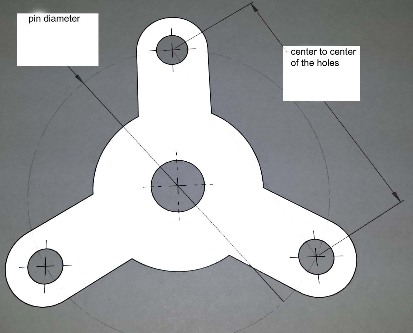
Flat Flange:
- We may need a flange measurement to identify the correct one, see the diagrams below for how to measure 3-Bolt, 4-Bolt, and 6-Bolt Flange patterns.
- ANY RUBBER GUIBO COUPLERS MUST BE REMOVED BEFORE MEASURING
Rear Pinion Yoke and Flange Measurement Diagrams:
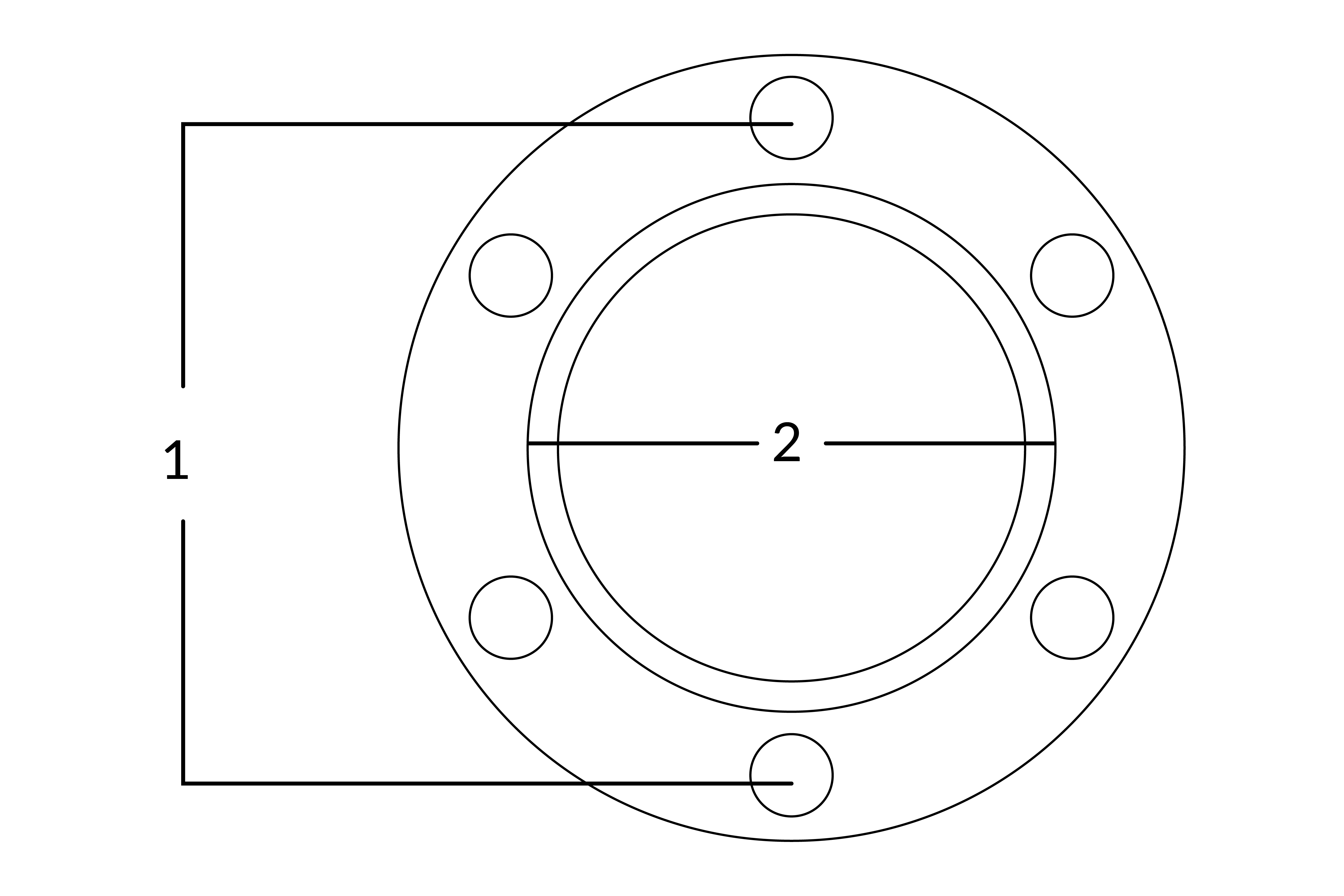
Measure Flange Pattern:
- Center of the bolt to center of the bolt -Horizontal
- Centering pilot diameter (Can be male OD of Female ID- Must Specify)
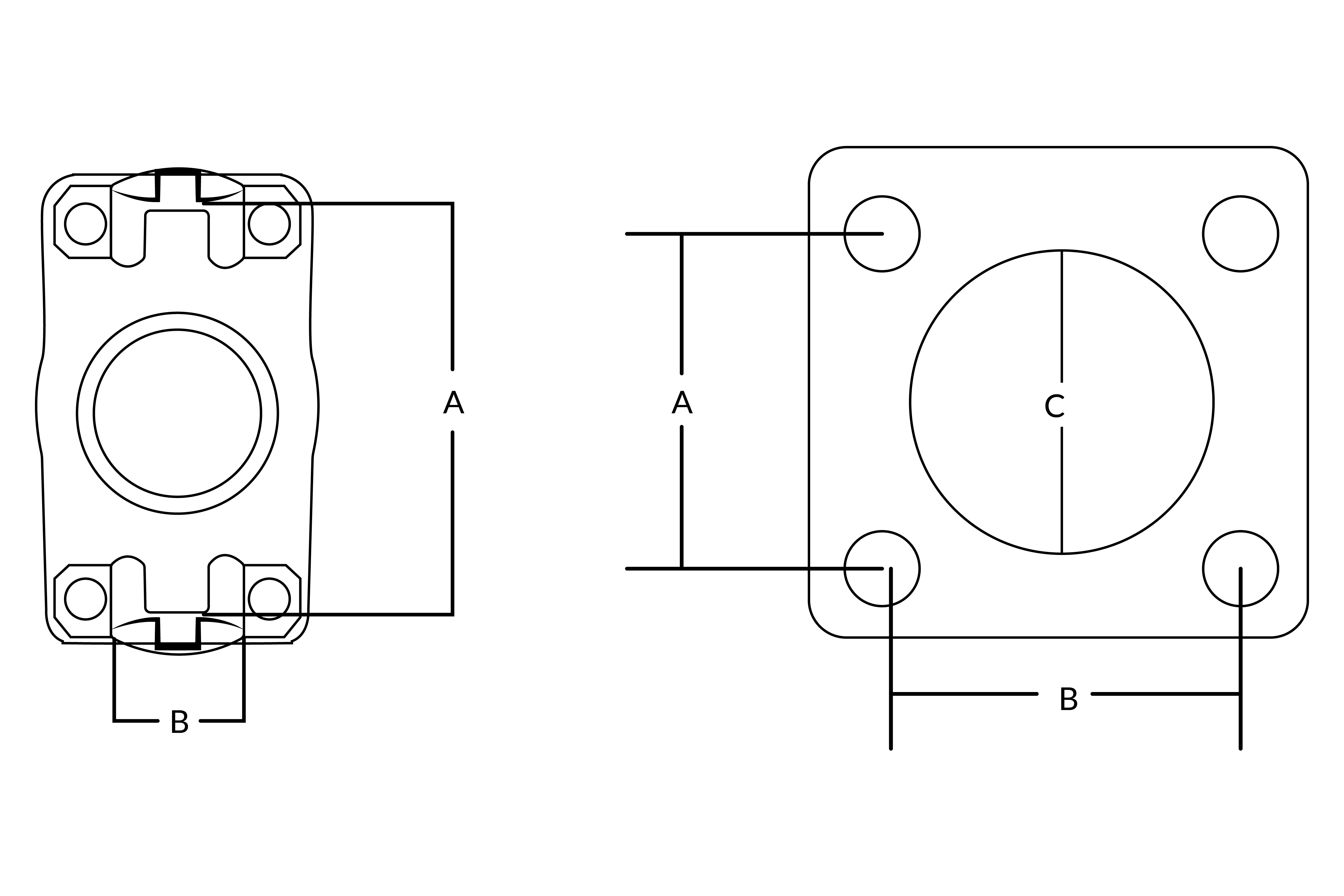
Measure Flange Pattern:
- Center of the bolt to center of the bolt -Vertical
- Center of the bolt to center of the bolt -Horizontal
- Centering pilot hole diameter (Can be male OD of Female ID- Must Specify)
Custom Driveshaft Quotes are created on an individual basis, we take all of the information you provide into account to build you a driveshaft based on your specific needs. This takes some time, and we may need to contact you for additional information or specifics before we can finalize it for you. Please allow us 2-3 days to create your quote and send it to you for approval.
Once you have the measurements and vehicle specific information
↓ CLICK HERE ↓